How do you build an IAP (Instrument Approach Procedure)?? Explained!
So how are IAP’s created you ask? Well good question, but I’m afraid the answer isn’t as easy as the question. I will try to give an overall brief explanation on how this is accomplished. Going into full detail would have you reading for hours only to arrive at the end and ask yourself “what in the heck did I just read and what was it even about”? Though I will try my best to provide you with enough details so you can grasp the enormous task that is creating an approach and turning it into the final product that you, the end users see. If you haven’t yet read my short tutorial (w/ color picture!) on how to read an IAP, head on over there now with this link >> How do I read an IAP (Instrument Approach Procedure)? Explained within!
So let’s get started!
Every major airport in the world has an instrument procedure, sometimes multiple to a single runway. But who decides what these will look like, how they will be flown, who can fly them, what altitudes a pilot will maintain? Welcome to the very SMALL world of professionals known as TERPS (Terminal Instrument Procedures). How many people are qualified in this profession? While I have no source to support this claim, there are between 250-500 TERPsters worldwide. What types of tools do we use? Well that depends on where you work and what equipment you have available to you, but, most work with charts and engineering tools, such as a drafting table, compass, erasing shield, protractors, angled triangles, and engineers ruler and then there are software based programs (which are SO much faster and better).
I personally do not do any manual drawing, I use a software product that is capable of building a workspace anywhere in the world in just seconds. Every 28 days I upload all the newest data concerning any new reported or satellite found obstacles all around the world as well as new terrain data, airport data, naviad and waypoints data and visual reference data. This process is not fast and usually takes most of the day when done.
Alright, so now we have a job to do. XXXX airport is installing a new VOR, it is currently being flight checked and will become operational at the beginning of 2018. This VOR is NOT within 75 feet of the VOR being replaced, so what does that mean? That means that all CURRENT procedures associated with the VOR being replaced MUST be reproduced.
So what do I need to get started? First and foremost I need the VOR coordinates, which I will enter into my program with a 0.005 accuracy. I will then go through the latest Aerodrome IAP supplement and ensure I have all the correct data relating to the airport elevation, threshold elevations, runway true bearing, updated magnetic variations and so forth. Once all that is complete and the data is input, time to build. Now, ATC and or the Airport Authority will tell us what they want, how they want it and so forth and we will do our best to build it to that. But due to certain limitations, rules, obstacles and terrain, they might not get exactly that.
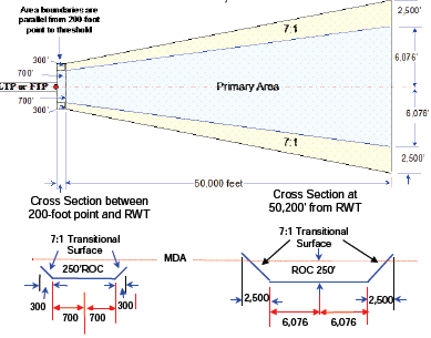
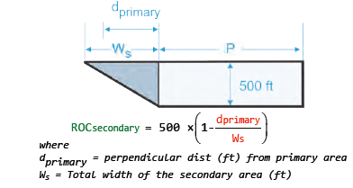
So building a VOR, there are a few things that I need to know. First off, is the VOR on the airport or within 1 mile of it, is there going to be a FAF (Final Approach Fix), will this procedure include a tear drop or procedure turn, will there be holding in lieu of procedure turn. Each one of these has their own set of criteria on what is allowed. For the sake of easy, we will say this VOR is on the airport and will have a FAF. There are multiple segments in a procedure, The Initial, Intermediate, Final and Missed. The first area we will build is the final segment. You build this segment first so that you don’t build all the way into the final segment to learn that the way you have jammed yourself up won’t work, making you “erase” all the previous work. Things we have to consider is ROC (Required Obstacle Clearance), which in this case, is a minimum 250ft in the primary area and tapers to lower in the secondary are. See illustration.
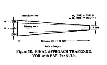
For the clearance in the secondary, we use a simple formula, ROC= 250X (WS-d/WS) where Ws= width of the secondary and D = distance from inner edge

So if this is a perfect world approach and there is nothing in the way, the pilot only need to be 250ft from the ground. But that is rarely the case. For this approach to be considered a “straight in” approach, the angle convergence of the final course and extended runway centerline shall no exceed 30 degrees. So in essence, if we are landing on runway 28 (280), to most left or right you would be to line up with the runway is 30 degrees, so either 250 or 310 on the final course. There are additional rules that govern how and where an aircraft may intercept the extended runway centerline. Your goal is always to have the aircraft intercept the extended centerline 3000ft from the runway with no more than a 30 degree turn, but you can get as far as 5200ft or as close as the threshold.

The next section we will build is the missed approach. This portion is built second because there may be penetrations that would require you to move your final approach segment. Though most of the time, you can solve this issue by adjusting you MDA (minimum descent altitude) to alleviate a certain amount of penetration. When building this area, we must take into consideration things such as the Straight Missed Approach Area, Straight Missed Approach Obstacle Clearance, Turning Missed Approach Area and Obstacle Clearance, a combination of the two and the end of the missed approach. When the missed approach course is within 15 degrees of the final approach course, it is considered a straight missed approach.
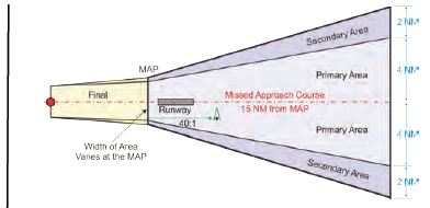
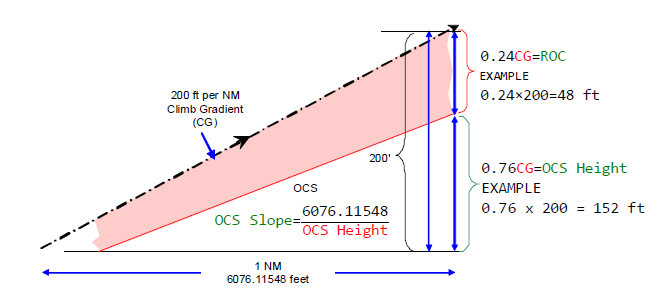
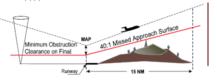
We must evaluate a 40:1 surface from the MAP (missed approach point) all the way until the end of the missed approach (clearance limit).
Here are some additional trapezoids in which we will create to evaluate a turning missed approach.

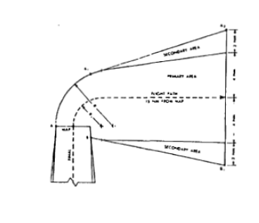

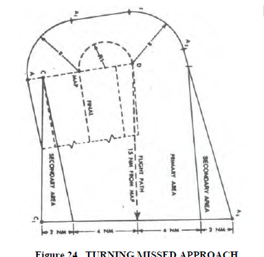
So lets say we have an obstacle in the missed approach area, but we want to turn the aircraft. We have to figure out, at what point we can turn them. What we need are the MDA (360ft) the height of the obstacle (1098ft MSL) and where the obstacle is. In this case, we will place it in section 2, 3NM from the near edge of the section. First, we will want to know what the MSL height is at the near edge, we do this by getting the distance in feet 18,228ft (3NM) and divide that by 40 (our 40:1 slope) and we get 456ft. We will then take our obstacle height (1098ft MSL) and subtract the 456ft. We get 642ft MSL. Remember the 250ft of ROC we always us? We will add that to our 642ft MSL and get 892ft in which you round up to the next highest 20ft and get 900ft MSL to start our turn. Now lets find the height of climb from the MDA to 900ft MSL. 900 – 360 = 540ft to climb. This will allow us to now find our section one length, 540ft x 40 = 21600ft. So now we have the first part of our missed approach, and we can start the missed approach instructions like this “Climb to 900’ before starting right turn to……”

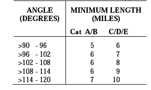
So now that we’ve finished up our missed (yes, I draw out and got the aircraft to a holding pattern without you), we need to start on the Intermediate Segment. This segment is what connects the Initial to the Final. This segment can be straight, an ARC or a Procedure Turn. If using a straight segment, unless the FAF is the navigation facility (VOR in this case, but since we are using an on airport VOR, doesn’t apply) the course must be in line with the FAC (final approach course) If the facility is the FAF, you can have up to a 30 degree turn connecting the two segment. In this segment, our required obstacle clearance is now 500ft. If there is a turn to enter this segment from the initial segment, you must adhere to certain required lengths.
And here is our ROC formula
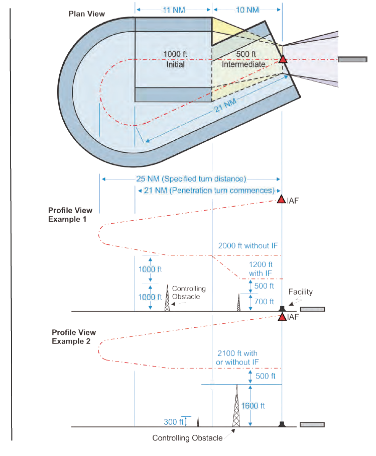
If we are creating a Procedure Turn, of course it comes with its own set of rules, the basic are length, such as the optimal being 10NM, max being 15NM and min being 5 NM. There are rules for whether the intermediate area is within the PT and the FAF is a facility

or if it is within the PT but the FAF is not a facility
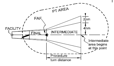
and it goes on and on and on and on with rules.
This is getting long, so lets cut now to the Initial Segment. This segment is by far the EASIEST to build, while it still has it rules, the aircraft height is usually so far above any terrain or obstacles that you can build it however you want. The main rule here is the ROC, 1000ft.
So before I end this quick little lesson, here are a few of the most common things we need to figure out and their formulas. Give them a try and see if you can get the answer!
Calculating Descent Angles-

Determining straight in FAF or step down fix location to achieve a specified design angle
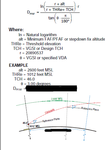
Calculating VDA’s (not conforming to straight in criteria)

Calculating VDA’s (conforming to straight in criteria)

Here are just some random other things you might find interesting. Have a good one!